Guidelines of transformer differential stability check
Transformer above 2 MVA are normally provided with differential protection scheme. The relay can be of static type(DTH31- Alsthom) or numerical type( 7 UT- Sag )
The relays have to be tested as per the procedure mentioned in manuals.The procedure mention below enables the testing engineer to confirm the correctness wiring.
Expected short circuit current can be calculated from the % impedance of the transformer.
e.g. Consider a transformer of 10 MVA, 132 KV /11 KV, % impedance – 13 %
Calculated primary full load current -43.8 A
Calculated secondary full load current- 525 A
17.16 KV applied with secondary short circuited will give a full load current.
If we applied 415 V to the primary we will obtain a 2.5%, Primary=1.05 and correspondingly 12.6 amp in the secondary.
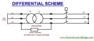
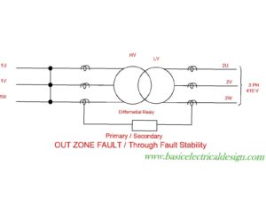
Connect the circuit as shown in figure 1 & 2


For numerical differential relays (e.g. 7UT512/3) the currents obtain by the above method will not be enough for all result to be displayed- eg line angles etc.
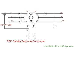
Hence a scheme with 33KV as source and 132 KV side short circuited can be employed.
Connect the circuit as shown in figure 3

The short circuit test can be switched on / off with the breaker on secondary side.
Measurements to be made on the differential system
- Measure the currents at the CT terminals and ensure that ratio is properly maintained (for both primary and secondary winding).
- Measure the differential, resistance currents.
- Currents measured in the transformer differential circuit must be minimal (1 to 3 % of the line currents).
- If the differential currents are more than above mentioned values then the following
Table must be checked and wiring mistake rectified.
Pilot Currents Operating Currents
[ultimatetables 1 /]
Where I= line current in CT secondary.
Transformer Stability of REF circuit
Connect the circuit as per figure 4.

Switch on the supply and measure the currents at the relay terminals.
See that the differential current is minimal. If the measured differential current is high then reserve the polarity of one CT (Preferably NCT). Recheck the stability.
